ASTM B406
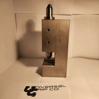
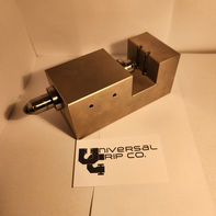
Cemented Carbides Transverse Rupture Fixture


ASTM B406 – Transverse Rupture Strength of Cemented Carbides - PDF
Overview
ASTM B406 is the standard test method used to determine the transverse rupture strength (TRS) of cemented carbides, such as tungsten carbide. These materials are extremely hard and brittle, often used in cutting tools, wear parts, and dies. This test evaluates a material’s resistance to breaking under flexural stress using a three-point bending setup.
While it does not provide a true tensile strength value, TRS is a useful and repeatable quality control metric for comparing different carbide grades or manufacturing processes.
Test Fixture and Equipment
The test is performed using a three-point bending fixture mounted in a universal testing machine. The fixture must meet these specifications:
-
Support span: 25.4 mm (1.000 inch)
-
Support roller diameter: 3.175 mm (0.125 inch)
-
Loading nose diameter: 3.175 mm (0.125 inch)
-
Material: Hardened steel or tungsten carbide rollers
-
Alignment: Rollers and loading nose must be aligned precisely to ensure accurate load application and avoid twisting forces
A constant crosshead speed of 0.051 mm/s (0.002 in/s) is recommended for applying the load during the test.
Specimen Requirements
-
Length: 31.8 mm (1.250 inch)
-
Width: 6.35 mm (0.250 inch)
-
Thickness: 1.59 mm (0.063 inch)
The specimen should be ground on all surfaces, free from cracks, chips, or visible defects. Surface quality is essential for consistent results, as edge flaws can act as fracture initiation points.
Test Procedure
-
Measure the specimen dimensions (width and thickness) accurately with a micrometer.
-
Place the specimen on the two lower support rollers of the three-point bend fixture.
-
Center the upper loading nose above the specimen.
-
Begin loading at a constant crosshead speed until the specimen fractures.
-
Record the maximum load (F) at the point of rupture.
TRS Calculation
The transverse rupture strength (TRS) is calculated using the following formula:
TRS = (3 × F × L) / (2 × b × d²)
Where:
-
TRS = transverse rupture strength in megapascals (MPa)
-
F = maximum fracture load in newtons (N)
-
L = support span in millimeters (mm)
-
b = specimen width in millimeters (mm)
-
d = specimen thickness in millimeters (mm)
Example Calculation
If F = 1500 N, L = 25.4 mm, b = 6.35 mm, and d = 1.59 mm:
TRS = (3 × 1500 × 25.4) / (2 × 6.35 × 1.59²)
TRS = 114300 / (2 × 6.35 × 2.5281)
TRS = 114300 / 32.102
TRS ≈ 3,559 MPa
This result reflects the flexural strength of the cemented carbide under controlled conditions.
Applications and Use Cases
-
Quality control for sintered carbide products
-
Material development and performance benchmarking
-
Comparative testing between different carbide grades or manufacturing lots
-
Verification of production consistency in tooling and wear-part industries
This test is widely used in the tooling, automotive, aerospace, and powder metallurgy industries.
Related Standards
The following standards are similar to or used in conjunction with ASTM B406:
-
ASTM B528 – Alternate method for TRS of sintered metal carbides with emphasis on test reproducibility
-
ASTM C1161 – Flexural strength testing of advanced ceramics (also uses a three-point or four-point bend method)
-
ASTM E290 – Bend testing of metallic materials (more for ductility than rupture strength)
-
ISO 3327 – International standard for TRS of hardmetals, similar in scope and method to ASTM B406
Summary
ASTM B406 provides a clear, repeatable method to measure the transverse rupture strength of cemented carbides using a precise three-point bend setup. While it does not represent a material’s tensile or compressive strength, it serves as a valuable quality indicator for brittle, sintered materials like tungsten carbide. For manufacturers of tools, dies, and wear-resistant components, it is a vital part of the quality control process.


