
ISO 527-5
Tensile Testing of Unidirectional Fibre-Reinforced Composites
Written by Chris Thomas, Universal Grip Company · Reviewed by Frank Bertini · Updated October 24, 2026
ISO 527-5 is the international standard for the tensile properties of unidirectional fibre-reinforced plastic composites: carbon, glass or aramid fibres in a thermoset or thermoplastic matrix, with all the fibres running one way. It is the ISO twin of ASTM D3039 and the test that produces the 0° tensile strength, the 0° modulus E1, the 90° (transverse) strength and modulus E2 and the major Poisson's ratio ν12 that every laminate analysis, every aerospace allowable and every material data sheet for a prepreg or pultrusion is built on. It sits on the general principles of ISO 527-1 and uses two rectangular, end-tabbed coupons: Type A for fibres parallel to the load and Type B for fibres perpendicular to it.
There is almost no complete guide to this standard on the web, and the one equipment technote that prints the coupon dimensions has the two types swapped. This page gives the correct dimension table for Type A and Type B with the tab and grip-distance geometry, the end-tab rules (square ends, 0.5 to 2 mm thick, at least 50 mm long), the 2 mm/min speed, the 0.05 to 0.25 % modulus window, which failures count and which do not, the alignment requirement, the load-cell arithmetic that makes a 100 kN frame necessary for 0° carbon and a 5 kN cell necessary for 90° coupons on the same frame, a worked example, the common errors, a numeric comparison with D3039, and the grips, extensometers and machines Universal Grip supplies for the test.
In this guide: What ISO 527-5 Covers · Type A and Type B Coupons: the Correct Dimensions · Specimen Preparation and End Tabs · Machine, Grips, Alignment and Strain Measurement · Test Speed, Modulus Window and Valid Failures · Step-by-Step Procedure · Calculations and a Worked Example · Common Errors and Their Size · ISO 527-5 vs ASTM D3039 · Equipment for ISO 527-5: Grips, Capacity, Extensometers and Machines · FAQ
What ISO 527-5 Covers
ISO 527-5:2021 specifies the test conditions for the tensile properties of unidirectional fibre-reinforced plastic composites, based on the general principles of ISO 527-1. The reinforcement may be aligned fibres, rovings, unidirectional fabrics or unidirectional tapes of carbon, glass, aramid or similar fibres; the matrix may be a thermoset or a thermoplastic, and prepregs are included. The properties determined are the tensile strength, the tensile modulus, the Poisson's ratios, the strain at break and the other stress and strain points defined in ISO 527-1.
-
Unidirectional only. A laminate built from unidirectional plies at different angles, a woven fabric laminate, a random-mat composite or a short-fibre moulding goes to ISO 527-4. The rule is simple: all fibres in one direction, use Part 5; anything else that is symmetric and balanced, use Part 4.
-
Two coupon types. Type A is cut with the fibres along the loading axis (0°) and gives the fibre-dominated properties; Type B is cut with the fibres across the axis (90°) and gives the matrix- and interface-dominated transverse properties. Both are rectangular strips with bonded end tabs.
-
Failure mode is part of the method. The standard applies to materials that fail in an acceptable mode within the gauge section; a coupon that fails in the tabs or at the grips does not give an ISO 527-5 result.
-
Current edition is the third, ISO 527-5:2021, which replaced the 2009 edition, itself a revision of the original 1997 text. It is adopted unchanged as EN ISO 527-5, BS EN ISO 527-5 and DIN EN ISO 527-5. The 2021 edition aligns the part with ISO 527-1:2019 and with the 2021 revision of Part 4.
Related ISO composite methods are ISO 14126 (compression), ISO 14129 (±45° in-plane shear) and ISO 14130 (short-beam shear); the ISO standards index lists every ISO method we equip.
Type A and Type B Coupons: the Correct Dimensions
Both coupons are 250 mm long rectangular strips with end tabs on both faces, a 50 mm gauge length and a grip-to-grip distance of 136 mm. The only differences are the fibre direction, the width and the thickness. Dimensions in millimetres:
-
Type A (0°, fibres parallel to the load): overall length 250, width 15 ± 0.5, thickness 1 ± 0.2, tab length ≥ 50 at each end, tab thickness 0.5 to 2, gauge length L0 50 ± 1, initial distance between grips L 136 ± 1.
-
Type B (90°, fibres perpendicular to the load): overall length 250, width 25 ± 0.5, thickness 2 ± 0.2, tab length ≥ 50, tab thickness 0.5 to 2, L0 50 ± 1, L 136 ± 1.
-
Why the geometry differs. The 0° coupon is narrow and thin because fibre-direction strength is enormous: 15 × 1 mm of carbon/epoxy already carries 30 kN or more at break, and a thicker coupon would need grips and a frame that few labs own. The 90° coupon is wider and thicker because transverse strength is low (a few tens of megapascals) and a 1 mm coupon would give a force too small to measure accurately and would be damaged by handling.
-
The 7 mm rule. With 50 mm tabs on a 250 mm coupon the free length between the tabs is 150 mm; setting the grips at 136 mm puts the jaw edge 7 mm inside each tab, so the grips never close on bare laminate. If your tabs are longer, keep L at 136 mm and let the extra tab length sit outside the jaws.
Width and thickness are measured at three points in the gauge region with a micrometer reading to 0.01 mm and the mean cross-section is used. On a 1 mm coupon a thickness error of 0.02 mm is 2 % in every stress and modulus value, so measure the laminate, never the tab, and never assume the nominal ply thickness. The dimension error that tabs introduce is a frequent reason for 0° modulus results that disagree between labs by several percent.
Specimen Preparation and End Tabs
Panels are moulded per ISO 1268 (autoclave, press or resin-infusion as the material specifies), with the fibre direction marked before cutting. Coupons are cut with a diamond wheel or a water-jet with the edges parallel and perpendicular to the fibre direction, free of delamination, fibre pull-out and heat damage, because an edge flaw on a 90° coupon is a crack starter and on a 0° coupon causes premature longitudinal splitting. At least five valid specimens are required for each type and condition; more are needed if the confidence interval demanded by the material specification is not met.
-
Tabs are required on both types. They spread the clamping load, protect the laminate from the jaw faces and move the stress concentration away from the grip. Tab length is at least 50 mm, thickness 0.5 to 2 mm.
-
Square ends, no bevel. ISO 527-5 tabs end perpendicular to the specimen axis. The 5 to 90° bevel that ASTM D3039 allows is not used; a tapered tab on an ISO job is a reportable deviation, not an option.
-
Tab material. Cross-ply or ±45° glass-fibre/epoxy is the usual choice for both coupon types; it is stiff enough to carry the clamping load, soft enough not to cut the laminate and bonds well. Aluminium tabs are used on some thermoplastic laminates; same-material tabs are used where thermal expansion mismatch at hot or cold test temperatures would stress the bond.
-
Adhesive. A structural epoxy, film or paste, cured at a temperature below the laminate's glass transition and with a glass transition above the test temperature. Bond in a jig that keeps the tabs aligned and the adhesive line uniform; a tab that sits 0.1 mm proud on one side bends the coupon in the grips.
Conditioning follows ISO 291: 23 ± 2 °C and 50 ± 10 % relative humidity, normally for at least 16 hours, unless the material specification requires a hot/wet conditioning. Aerospace programmes typically test the same laminate dry, and after moisture saturation at 70 °C and 85 % RH, and then at elevated temperature in a chamber; the tabs and adhesive must survive that programme too.
Machine, Grips, Alignment and Strain Measurement
-
Force measurement: ISO 7500-1 class 1 (± 1 % of reading) over the range used. This is the trap on a 100 kN frame: the class 1 range of a 100 kN cell typically starts at 1 to 2 kN, so a Type B glass coupon breaking at 1.5 kN needs a second, smaller load cell. See our calibration page.
-
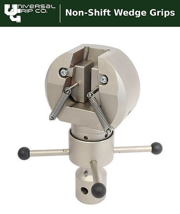
Grips: must hold the tabbed ends without slipping and without crushing the tab, with faces that cover the full 50 mm tab, and must keep the specimen axis on the load line. Hydraulic wedge grips are the standard choice for 0° carbon because the clamping force is set and maintained independently of the tensile load; mechanical wedge grips work for glass and for Type B; pneumatic grips are used for thin Type B coupons where a few kilonewtons are enough. The gripping pressure or torque used is recorded and reported.
-
Alignment: ISO 23788 describes the strain-gauged alignment coupon and the percentage-bending calculation. Bending of even 5 % lowers the apparent 0° strength by several percent and scatters the modulus, because the fibre-dominated coupon has almost no capacity to redistribute stress. Check alignment at installation and after any grip change; spherical seats or an adjustable alignment fixture in the load train are how it is corrected.
-
Extensometer: ISO 9513 class 1 over the 50 mm gauge length, or bonded strain gauges. The modulus window is 0.05 to 0.25 % strain, which on 50 mm is 25 to 125 µm of extension: the device must resolve about 1 µm. Contact clip-ons must be removed before the 0° failure, which is violent; a video extensometer or digital image correlation stays on to break and also gives the transverse strain for Poisson's ratio.
-
Transverse strain: Poisson's ratio needs a second strain channel across the width, from a biaxial clip-on, a transverse strain gauge or a video system tracking width as well as length. Type A gives the major ratio ν12, Type B the minor ratio ν21.
Test Speed, Modulus Window and Valid Failures
The test speed is 2 mm/min for the modulus and for strength on both coupon types. On the 136 mm grip distance that is a nominal 1.5 %/min, but because the tabbed ends carry almost no strain the actual strain rate in the gauge section is closer to 1 %/min, which is the ISO 527-1 intent. The tolerance on speed is ± 20 % at this end of ISO 527-1 Table 1, so the crosshead must run between 1.6 and 2.4 mm/min. Where a material specification allows a faster strength test, the modulus is still taken at 2 mm/min and the speed change is reported.
-
Tensile modulus: Et = (σ2 − σ1) ÷ (ε2 − ε1) with ε1 = 0.0005 and ε2 = 0.0025, by two-point chord or by regression over the window. For a 0° carbon coupon the curve stiffens slightly with strain, so the ISO window gives a modulus a little lower than the ASTM D3039 window of 0.1 to 0.3 %; the two are not interchangeable.
-
Tensile strength: σm = Fmax ÷ (b × h), the first local maximum; on a unidirectional coupon it is the maximum.
-
Strain at break: from the extensometer or strain gauge, not from crosshead travel.
-
Poisson's ratio: µ = −Δεn ÷ Δε over a strain interval wider than the modulus window so that the transverse strain is large enough to resolve.
Valid and invalid failures. For Type A the valid failure is fibre fracture in the gauge section, usually a brooming or explosive break; longitudinal splitting that accompanies fibre fracture is acceptable. For Type B the valid failure is a clean transverse matrix crack in the gauge section. A failure in the grips, within the tab, at the tab-to-gauge transition or by tab debond is invalid: the specimen is discarded, the cause is corrected and a replacement is tested. ISO 527-5 does not use the three-letter failure codes of D3039; the failure mode and location are described in the report.
-
Tab debond or failure at the tab edge: adhesive or surface preparation problem, tab too thin, or the grip pressure too low so the tab slips and peels. Re-bond, raise the clamping pressure, check the tab edge is square.
-
Failure in the grips: jaws closing on bare laminate (L not 136 mm), faces too aggressive for the tab, or pressure too high crushing the tab. Check L, change to a finer face, reduce the pressure.
Step-by-Step Procedure
-
Verify the machine: ISO 7500-1 class 1 force over the range you will use, extensometer class 1, alignment checked per ISO 23788.
-
Condition the coupons per ISO 291 or the material specification; measure width and thickness at three gauge-section points and compute the mean cross-section.
-
Mark the 50 mm gauge length or the extensometer contact points on the gauge section; mount the extensometer or confirm strain gauges and the transverse strain device.
-
Set the grips 136 mm apart; insert the coupon so that the jaw edges sit on the tabs, centred and parallel to the load axis; close the grips at the recorded pressure.
-
Apply a small preload, at most 0.05 % strain or 1 % of the expected strength, and zero the strain channels.
-
Run at 2 mm/min; record force, axial strain and transverse strain continuously; keep the modulus window well resolved (20 to 50 Hz is adequate).
-
If a contact extensometer is used, remove it after the modulus and Poisson's ratio interval and before the expected failure; run to break.
-
Record the failure mode and location; reject invalid failures and replace them so that at least five valid results are obtained.
-
Calculate σm, Et, εb and µ for each coupon; report individual values, mean, standard deviation and coefficient of variation, with the full report list below.
Calculations and a Worked Example
Type A, 0° carbon/epoxy. Width b = 15.03 mm, thickness h = 1.02 mm, so the cross-section A = 15.03 × 1.02 = 15.33 mm². The force at break is 36.4 kN. Tensile strength σm = 36,400 N ÷ 15.33 mm² = 2,374 MPa. In the modulus window the stress at 0.05 % strain is 68 MPa and at 0.25 % strain it is 352 MPa, so Et = (352 − 68) ÷ (0.0025 − 0.0005) = 284 ÷ 0.002 = 142,000 MPa = 142 GPa. Over the same 0.002 strain increment the transverse strain changed by −0.00062, so ν12 = 0.00062 ÷ 0.002 = 0.31.
Type B, 90° carbon/epoxy. b = 25.01 mm, h = 2.01 mm, A = 50.27 mm². Force at break 3.02 kN, so σm = 3,020 ÷ 50.27 = 60.1 MPa. Stress at 0.05 % strain 4.5 MPa and at 0.25 % strain 22.3 MPa: Et = 17.8 ÷ 0.002 = 8,900 MPa = 8.9 GPa. Note the force ratio between the two coupon types: 36.4 kN against 3.0 kN, a factor of twelve on the same frame.
-
Report per ISO 527-5: the part and edition; material, fibre and matrix, fibre volume fraction, lay-up and cure; coupon type, dimensions, tab material, thickness and adhesive; gripping system, faces and pressure; alignment method; strain devices and gauge length; speed; conditioning; number tested and number rejected with reasons; individual, mean and standard deviation values; failure modes and locations.
Common Errors and Their Size
-
Type A and Type B dimensions swapped. One widely circulated equipment technote prints Type A as 25 × 2 mm. A 25 × 2 mm 0° carbon coupon breaks at about 120 kN, not 35, and will stall or damage a 100 kN frame.
-
Thickness measured on the tab or taken from the ply count. A 0.05 mm error on a 1 mm coupon is 5 % in strength and modulus.
-
Modulus from the D3039 window. 0.1 to 0.3 % strain on a stiffening 0° curve reads 1 to 3 % higher than the ISO 0.05 to 0.25 % window; do not label it an ISO 527-5 modulus.
-
Bevelled tabs. Allowed by ASTM, not by ISO; the result is still a tensile strength but not an ISO 527-5 result.
-
Grips closing on bare laminate. Any L other than 136 mm with 50 mm tabs; expect grip failures and a strength 10 to 30 % low.
-
Load cell too large for Type B. A 100 kN cell reading 1.5 kN is at 1.5 % of range; most are not class 1 there. Fit a 5 or 10 kN cell.
-
Misalignment. 5 % bending costs several percent of 0° strength and widens the scatter; a coupon that always breaks at the same end is the symptom.
-
Crosshead strain. Grip, tab and frame compliance make the apparent modulus of a 142 GPa coupon read tens of percent low; ISO 527-5 requires an extensometer or strain gauges.
ISO 527-5 vs ASTM D3039
The two standards are close relatives and a 0° carbon coupon is practically the same size in both, which is why equipment pages call them equivalent. They are not: the modulus window, the tab geometry and the failure reporting differ, and a data sheet should name the one actually used.
-
Scope: ISO 527-5 unidirectional only; D3039 covers all balanced, symmetric polymer-matrix composites including unidirectional.
-
0° coupon: ISO Type A 250 × 15 × 1 mm; D3039 Table 2 recommends 250 × 15 × 1.0 mm. Essentially identical.
-
90° coupon: ISO Type B 250 × 25 × 2 mm; D3039 recommends 175 × 25 × 2.0 mm. The ISO coupon is 75 mm longer.
-
Tabs: ISO mandatory, ≥ 50 mm, 0.5 to 2 mm, square ends; ASTM recommended, 56 mm (0°) or 25 mm (90°), 1.5 mm typical, bevel 5 to 90° with 7° common.
-
Grip distance: ISO fixed at 136 ± 1 mm; ASTM not fixed.
-
Speed: ISO 2 mm/min; ASTM 2 mm/min or 0.01 /min strain rate, with failure within 1 to 10 minutes.
-
Modulus: ISO chord 0.05 to 0.25 %; ASTM chord 0.1 to 0.3 % (1,000 to 3,000 µε).
-
Extensometer: ISO 9513 class 1; ASTM E83 class B-1.
-
Alignment: ISO 23788; ASTM E1012.
-
Failure reporting: ISO describes mode and location; ASTM uses three-letter codes (LGM, XGM, GAT and so on).
The aerospace equivalents EN 2561 (0° carbon) and EN 2597 (90°) and the Airbus AITM 1-0007 method follow the ISO geometry and are often run on the same equipment; our ASTM D3039 guide covers the ASTM side in the same depth.
Equipment for ISO 527-5: Grips, Capacity, Extensometers and Machines
Capacity first. Multiply the cross-section by the expected strength. Type A carbon/epoxy at 2,000 to 2,500 MPa on 15 mm² is 30 to 38 kN; Type A glass/epoxy at 1,000 to 1,200 MPa is 15 to 18 kN; a 2 mm-thick 0° carbon coupon is 60 to 75 kN. Type B carbon at 40 to 80 MPa on 50 mm² is 2 to 4 kN and Type B glass 1.5 to 3 kN. A 100 kN frame therefore covers everything up to 2 mm 0° carbon, but the 90° work needs a 5 or 10 kN load cell on the same frame so that the force is read in a class 1 range.
-
Grips. Hydraulic wedge grips at 100 kN with serrated or diamond-coated faces at least 50 mm long for Type A carbon: the clamping force is set by pressure, recorded as the standard asks, and does not relax as the tab compresses. Mechanical wedge grips for Type A glass and for Type B coupons up to about 50 kN, with fine serrated faces on tabs. Pneumatic grips with rubber or fine-serrated faces for thin Type B glass coupons at a few kilonewtons, where constant air pressure prevents the slip that a screw grip allows. Faces must cover the whole tab; a face shorter than the tab leaves an unsupported tab edge and causes transition failures.
-
Alignment. Spherical couplings or an adjustable alignment fixture between the grips and the load train, verified with a strain-gauged coupon per ISO 23788; we supply alignment-checked load trains with our grips and adapters for any machine brand.
-
Extensometers. A clip-on extensometer of ISO 9513 class 1 over 50 mm for the modulus, removed before break; a biaxial clip-on for Poisson's ratio; or a video extensometer or the Vector 3D DIC extensometer that measures axial and transverse strain to failure without touching the coupon and works through a chamber window. The video versus clip-on comparison explains when each is the better buy.
-
Machines. A 100 kN benchtop UTM covers Type A carbon at nominal thickness; a 50 kN benchtop UTM covers glass and all Type B work; a 200 kN floor-standing UTM is the choice for 2 mm 0° carbon, thick pultrusions and labs that also run ISO 527-4 tabbed strips. All are supplied with ISO 7500-1 class 1 calibration and a second low-range load cell when required.
-
Environmental chambers. Temperature chambers from −70 to +350 °C with chamber-rated grips and pull rods, and a window for the video extensometer, for the hot/wet conditioning programmes that aerospace specifications require.
See our tensile grips range and the composites fixture buyer's guide for the rest of the composite fixtures.
ISO 527-5 FAQ
What is ISO 527-5?
ISO 527-5 is the international standard for tensile testing of unidirectional fibre-reinforced plastic composites. It uses two end-tabbed rectangular coupons, Type A (0°) and Type B (90°), tested at 2 mm/min to give tensile strength, tensile modulus over 0.05 to 0.25 % strain, strain at break and Poisson's ratio. The current edition is ISO 527-5:2021.
What are the ISO 527-5 Type A and Type B specimen dimensions?
Type A (fibres parallel to the load) is 250 mm long, 15 ± 0.5 mm wide and 1 ± 0.2 mm thick. Type B (fibres perpendicular) is 250 mm long, 25 ± 0.5 mm wide and 2 ± 0.2 mm thick. Both have end tabs at least 50 mm long and 0.5 to 2 mm thick, a 50 mm gauge length and a grip distance of 136 mm.
What is the test speed for ISO 527-5?
2 mm/min for both the modulus and the strength on both coupon types, held within ± 20 %. With the tabbed ends carrying little strain, that gives roughly 1 %/min in the gauge section, which is the ISO 527-1 intent.
How is the modulus calculated in ISO 527-5?
As the chord or regression slope between 0.05 % and 0.25 % strain: Et = (σ2 − σ1) ÷ (0.0025 − 0.0005), using an ISO 9513 class 1 extensometer or strain gauges over the 50 mm gauge length. ASTM D3039 uses 0.1 to 0.3 %, so the two values are not interchangeable.
Are end tabs required for ISO 527-5?
Yes, on both Type A and Type B coupons: at least 50 mm long, 0.5 to 2 mm thick, bonded with a structural adhesive and with square ends. The bevelled tabs permitted by ASTM D3039 are not used in ISO 527-5.
Why is the grip distance 136 mm?
A 250 mm coupon with 50 mm tabs has 150 mm of free laminate between the tabs. Grips set 136 mm apart close 7 mm inside each tab, so the jaws never bear on bare laminate and the whole tab edge is supported.
Which failures are valid in ISO 527-5?
Type A: fibre fracture in the gauge section, usually explosive, with longitudinal splitting acceptable if the fibres have fractured. Type B: a clean transverse crack in the gauge section. Failures in the grips, in the tabs, at the tab edge or by tab debond are invalid and the coupon is replaced; at least five valid results are needed.
What machine capacity is needed for ISO 527-5?
Type A carbon/epoxy breaks at 30 to 38 kN (15 × 1 mm at 2,000 to 2,500 MPa), glass at 15 to 18 kN, and a 2 mm 0° carbon coupon at 60 to 75 kN, so a 100 kN frame is the norm. Type B coupons break at only 1.5 to 4 kN and need a 5 or 10 kN load cell on the same frame to stay in the class 1 force range.
What grips are used for ISO 527-5?
Hydraulic wedge grips with serrated or diamond faces covering the full 50 mm tab for 0° carbon, mechanical wedge grips for glass and Type B coupons, and pneumatic grips with rubber or fine faces for thin Type B glass. The gripping pressure is recorded, and alignment is verified per ISO 23788.
How is Poisson's ratio measured in ISO 527-5?
With a second strain channel across the width, from a biaxial clip-on extensometer, a transverse strain gauge or a video extensometer, evaluated over a strain interval wider than the modulus window. Type A gives the major ratio ν12 (typically 0.28 to 0.34 for carbon/epoxy); Type B gives the minor ratio ν21.
What is the difference between ISO 527-5 and ASTM D3039?
ISO 527-5 covers unidirectional laminates only, fixes the coupons at 250 × 15 × 1 mm (0°) and 250 × 25 × 2 mm (90°) with mandatory square-ended tabs and a 136 mm grip distance, and takes the modulus over 0.05 to 0.25 % strain. D3039 covers all balanced symmetric laminates, allows bevelled tabs, uses a 175 mm 90° coupon, takes the modulus over 0.1 to 0.3 % and reports three-letter failure codes. Results are similar but not equivalent.
When do I use ISO 527-4 instead of ISO 527-5?
ISO 527-5 is for laminates with all fibres in one direction. Multidirectional lay-ups, woven fabrics, random mats and short-fibre composites, whether isotropic or orthotropic, are tested to ISO 527-4 with its Type 1B, 2, 3 and 4 specimens.
Need hydraulic grips, an alignment-checked load train, a biaxial extensometer or a complete 100 kN system for ISO 527-5? Contact Universal Grip with your laminate, coupon type and expected strength and we will quote the right setup.