
ISO 527-1
Tensile Properties of Plastics: General Principles
Written by Chris Thomas, Universal Grip Company · Reviewed by Frank Bertini · Updated October 24, 2026
ISO 527-1 is the international standard for the general principles of tensile testing of plastics. It defines what is measured (tensile strength, yield stress, tensile modulus, strain at yield and break, nominal strain, Poisson's ratio), how the machine, grips and extensometer must perform, how fast the test runs, how specimens are conditioned and measured, how the results are calculated and what goes in the report. It does not define the specimens: those live in the companion parts, ISO 527-2 for moulded and extruded plastics, ISO 527-3 for films and sheets, ISO 527-4 for isotropic and orthotropic composites and ISO 527-5 for unidirectional composites. Every ISO plastics tensile result you see on a datasheet, from a polypropylene yield stress to a carbon-fibre laminate modulus, is run under the rules in this part.
This guide covers the current edition, ISO 527-1:2019, and the changes that matter from the 2012 revision; the full Table 1 speed list with its tolerances and the strain-rate arithmetic for choosing a speed; the 0.05 to 0.25 % chord modulus and why an ISO 9513 class 1 extensometer is mandatory for it; the preload rule; conditioning under ISO 291; the step-by-step procedure; every formula with a worked example; the common errors and how big they are; a numeric comparison with ASTM D638; and the grips, extensometers, cutting equipment and machines Universal Grip supplies for the test. The plastics testing page gives the lab overview and the ISO standards hub lists every ISO method we equip.
In this guide: What ISO 527-1 Covers and the Five Parts of ISO 527 · Editions: 1993, 2012, 2019 and What Changed · Test Speeds: Table 1 and the Strain-Rate Arithmetic · Tensile Modulus: the 0.05 to 0.25 % Chord · Machine, Grips and Alignment Requirements · Conditioning (ISO 291) and the Preload Rule · Step-by-Step Procedure · Formulas and a Worked Example · Common Errors and How Big They Are · ISO 527-1 vs ASTM D638: the Numbers · Equipment for ISO 527-1: Grips, Extensometers, Machines · FAQ
What ISO 527-1 Covers and the Five Parts of ISO 527
ISO 527-1 applies to rigid and semi-rigid plastics: thermoplastic moulding, extrusion and casting compounds, filled or unfilled; thermosets and laminates; fibre-reinforced thermoset and thermoplastic composites including prepregs; and thermotropic liquid-crystal polymers. It excludes rigid cellular plastics (ISO 1926) and sandwich panels with cellular cores. Rubber and thermoplastic elastomers that stretch to hundreds of percent go to ISO 37, and flexible foams to ISO 1798. The standard is a 'general principles' document, which is why it is paired with a specimen part:
-
ISO 527-1 (general principles): definitions, apparatus classes, speeds, conditioning, procedure, calculation and report. Current edition 2019.
-
ISO 527-2 (moulding and extrusion plastics): the multipurpose dumbbell A1 (formerly 1A), the machined A2 (formerly 1B), the reduced-scale 1BA and 1BB and the small 5A and 5B specimens. Thickness 1 mm and above. Current edition 2025.
-
ISO 527-3 (films and sheets): strips and small dumbbells for material under 1 mm thick, tested in line-contact or rubber-faced grips.
-
ISO 527-4 (isotropic and orthotropic composites): rectangular strips with and without end tabs for glass-mat, fabric and short-fibre composites.
-
ISO 527-5 (unidirectional composites): the 0° and 90° tabbed coupons for carbon and glass laminates, the ISO twin of ASTM D3039.
The properties the standard defines are the tensile stress σ (force over the original cross-section), the strain ε measured over the gauge length by an extensometer, the nominal strain εt derived from grip separation, the tensile modulus Et, the yield stress σy and strain at yield εy, the tensile strength σm (since 2012 the first local maximum on the curve, not the overall maximum), the stress at break σb, the strain at break εb or nominal strain at break εtb, the stress at a given strain σx (for example σ50 for ductile films) and Poisson's ratio µ. JIS K 7161 is technically identical, so a result reported to either is the same test.
Editions: 1993, 2012, 2019 and What Changed
The first edition of 1993 is the one most free PDFs on the internet still show, and several equipment pages still quote its values. The 2012 second edition was a major technical revision and is the basis of everything in use today; the 2019 third edition is the current one, an alignment and editorial update that kept the 2012 technical content. A further revision is at the working-draft stage, so check the edition on any document you are asked to test to. The 2012 changes you need to know are:
-
Preferred gauge length of the multipurpose specimen raised from 50 to 75 mm. A 50 mm gauge is still permitted for quality control or when a specification calls for it, but strain at break on a 75 mm gauge is not comparable with a 50 mm result on the same material.
-
Tensile strength is the first local maximum on the stress-strain curve, not the global maximum. For a ductile polymer that yields at 50 MPa, necks, cold-draws and then strain-hardens to 60 MPa before breaking, σm is 50 MPa.
-
Nominal strain Method B. For materials that yield, the nominal strain after yield is the extensometer strain at yield plus the increase in grip separation divided by the initial grip distance; Method A takes nominal strain from grip separation for the whole test. Method B removes the error from the extensometer and the grip compliance in the elastic region.
-
Poisson's ratio added as a formal property, measured with two simultaneous strain devices over a strain interval wider than the modulus interval.
-
Definitions rewritten for computer-controlled machines, including the option to determine modulus by linear regression over the 0.05 to 0.25 % interval instead of the two-point chord.
ISO 527-2 was itself reissued in 2025, renaming the specimens to the ISO 20753 designations (Type 1A became A1, Type 1B became A2) with the dimensions unchanged; the ISO 527-2 guide has the full crosswalk.
Test Speeds: Table 1 and the Strain-Rate Arithmetic
ISO 527-1 Table 1 lists the permitted crosshead speeds; the specimen part or the material standard says which to use. The list is 0.125, 0.25, 0.5, 1, 2, 5, 10, 20, 50, 100, 200, 300 and 500 mm/min. The tolerance is ± 20 % on the slow speeds and ± 10 % on the fast ones, so a nominal 1 mm/min must be held between 0.8 and 1.2 mm/min and a nominal 50 mm/min between 45 and 55. Speed is a crosshead speed, not a strain rate, which is why the right speed depends on the specimen length between the grips:
-
Modulus: at a speed that gives a strain rate of about 1 % per minute in the gauge length. For the A1/A2 specimens with 115 mm between the grips that is 1 mm/min (1 ÷ 115 × 100 = 0.87 %/min, which the standard rounds to 'approximately 1 %/min').
-
Smaller specimens scale down: 1BA and 5A with about 60 and 50 mm between the grips run modulus at 0.5 mm/min (0.83 and 1.0 %/min); 1BB and 5B with 24 and 20 mm run at 0.25 mm/min (1.0 and 1.25 %/min). This is why Table 1 starts at 0.125 mm/min, and why a page that quotes the speed range as '1 to 500 mm/min' has dropped the speeds needed for small specimens.
-
Yield, strength and strain at break: at the speed in the specimen part or material standard, in practice 5 mm/min for rigid and brittle materials and 50 mm/min for ductile materials where a test at 5 mm/min to 300 % strain would take an hour.
-
Two-speed test: the standard allows the modulus to be measured at 1 mm/min to just past 0.25 % strain and the crosshead then switched to the higher speed for the rest of the test on the same specimen, which is how most computer-controlled labs run it.
A quick rule for any specimen: strain rate in %/min = speed in mm/min ÷ grip distance in mm × 100. The modulus of most thermoplastics rises with strain rate, by roughly 5 to 10 % per decade of rate, so running a modulus at 5 mm/min 'to save time' gives a value a few percent high and is not an ISO 527 modulus.
Tensile Modulus: the 0.05 to 0.25 % Chord
The tensile modulus is defined over a fixed strain window: Et = (σ2 − σ1) ÷ (ε2 − ε1) with ε1 = 0.0005 (0.05 %) and ε2 = 0.0025 (0.25 %). Either the two-point chord between those strains or a least-squares regression over all points in the window may be used, and the report should say which. There is no toe compensation and no tangent to the 'initial linear portion', which is the main difference from the ASTM D638 modulus. The window is deliberately low to stay in the near-linear region of stiff polymers, which makes the measurement demanding:
-
On a 75 mm gauge length the window is 37.5 to 187.5 µm of extension, a span of 150 µm; on 50 mm it is 25 to 125 µm.
-
The strain accuracy required is ± 1 % of the measured value, which on the 150 µm span is about 1.5 µm absolute at 75 mm and 1 µm at 50 mm. That is the ISO 9513 class 1 requirement, and it is why crosshead displacement, which includes the compliance of the grips, load cell and frame, can never be used for an ISO 527 modulus. A crosshead-based 'modulus' on a 4 mm polyamide bar typically reads 20 to 40 % low.
-
The force channel must be ISO 7500-1 class 1 (± 1 % of reading) over the range used. On a 10 kN cell, a 40 mm² polypropylene specimen at 0.25 % strain is carrying about 60 N; make sure the cell is class 1 at that load or fit a smaller cell.
-
The data rate must resolve the window. At 1 mm/min the crosshead takes about 10 s to pass through 150 µm of gauge extension, so 20 to 50 Hz gives 200 to 500 points for the regression.
Poisson's ratio µ = −εn ÷ ε, where εn is the strain in the width (b) or thickness (h) direction, needs a second extensometer and is evaluated over a strain interval wider than the modulus window so that the transverse strain is large enough to resolve. A biaxial clip-on or a video system that tracks width as well as length does it in one test.
Machine, Grips and Alignment Requirements
-
Force measurement: ISO 7500-1 class 1, ± 1 % of the indicated force over the range used; verify annually. See our calibration page.
-
Speed: any Table 1 speed within its tolerance, held constant under load; verify at the test speed with the controller's encoder or a dial gauge and stopwatch.
-
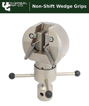
Grips: must hold the specimen so that its major axis coincides with the direction of pull through the centreline of the grip assembly, must not slip, and must not cause premature failure at the jaws. Self-tightening designs that maintain the clamping force as the specimen thins are preferred: pneumatic grips with maintained air pressure and mechanical wedge grips. The standard tells you to apply a slight tension before the second grip is tightened so that the specimen hangs straight and aligned.
-
Jaw breaks: a specimen that fails in the shoulders, slips, or breaks within about 10 mm of a jaw is discarded and replaced; the result is not averaged in.
-
Extensometer: ISO 9513 class 1 for modulus; ± 1 % of reading for other strains; must not slip or damage the specimen; a contact clip-on is acceptable, and for strain at break on ductile materials the clip-on is removed before failure or a long-travel or video extensometer is used.
-
Dimension measurement: width and thickness to ISO 16012 (micrometer, 0.02 mm resolution for 4 mm specimens, finer for thin ones) at the centre and within 5 mm of each end of the gauge length; moulded specimens are measured individually, never assumed to be nominal.
All Universal Grip grips are supplied with the adapter for Instron, MTS, ZwickRoell, Shimadzu, Galdabini, Mark-10 and other frames; the tensile grips page lists the full range and our grip selection guide walks through the choice.
Conditioning (ISO 291) and the Preload Rule
Unless the material standard says otherwise, specimens are conditioned and tested in the ISO 291 standard atmosphere of 23 ± 2 °C and 50 ± 10 % relative humidity (class 2; class 1 is ± 1 °C and ± 5 % for referee work). A minimum of 16 hours is the usual practice, and moisture-sensitive materials need far longer: a 4 mm polyamide 6.6 specimen reaches equilibrium moisture only after weeks at 50 % RH, which is why ISO 1110 accelerated conditioning (70 °C at 62 % RH) is used, and why polyamide datasheets quote 'dry as moulded' and 'conditioned' values that differ by a factor of two in modulus. Testing at other temperatures is done in an environmental chamber after soaking the specimen to temperature, typically 10 to 20 minutes for a 4 mm bar once the chamber has stabilised.
Preload. The specimen must not be substantially stressed before the test starts. For the modulus the prestress must keep the specimen below the 0.05 % strain where the window begins, and in practice a preload of no more than about 1 % of the expected tensile strength is used: on an A1 polypropylene specimen with σm of 35 MPa and a 40 mm² section, that is 0.35 MPa or 14 N. The preload exists to remove the slack in the grips so that the curve starts at a clean zero; too much of it moves the 0.05 % point and shifts the modulus.
Step-by-Step Procedure
-
1. Choose the specimen part (527-2, -3, -4 or -5), the specimen type and the gauge length (75 mm preferred for A1), and prepare at least five specimens per direction and property by moulding (ISO 294-1 or ISO 10724-1) or machining (ISO 2818). Mark the gauge length or fit targets if a video extensometer is used.
-
2. Condition per the material standard or ISO 291, and test in the same atmosphere.
-
3. Measure width and thickness at three positions in the gauge length and compute the cross-section A for each specimen.
-
4. Mount the specimen in self-tightening grips, square and centred, with the specified initial grip distance (115 mm for A1/A2); apply slight tension, tighten the second grip, and fit the class 1 extensometer at the gauge length.
-
5. Preload to no more than the limit above and zero the strain.
-
6. Run the modulus at 1 mm/min (or the scaled speed for small specimens) through 0.25 % strain.
-
7. Continue at the property speed (5 or 50 mm/min) to yield, break or the stated strain, recording force and extensometer strain; for ductile materials remove the clip-on at the safe limit and continue with nominal strain from grip separation (Method A or B).
-
8. Inspect the failure: discard and replace any specimen that broke in the shoulder, at the jaw or by slipping.
-
9. Calculate Et, σy, σm, σb, εy, εb or εtb and, if required, Poisson's ratio for each specimen, then the mean, standard deviation, coefficient of variation and 95 % confidence interval (ISO 2602).
-
10. Report the items in Clause 12: part and specimen type, preparation, orientation, conditioning, machine and extensometer class, grips and clamping pressure, speeds, individual and mean values, rejected specimens and why, and the date.
Formulas and a Worked Example
-
Stress: σ = F ÷ A, with F in newtons and A = b1 × h the original cross-section in mm², giving MPa.
-
Strain: ε = ΔL0 ÷ L0, the change in gauge length divided by the original gauge length; reported in %.
-
Nominal strain, Method A: εt = ΔL ÷ L, the change in grip separation over the initial grip distance L, from the start of the test.
-
Nominal strain, Method B: εt = εy + ΔL* ÷ L, the extensometer strain at yield plus the increase in grip separation after yield divided by L.
-
Tensile modulus: Et = (σ2 − σ1) ÷ (ε2 − ε1) at ε1 = 0.0005 and ε2 = 0.0025, or a regression slope over that interval.
-
Poisson's ratio: µ = −εn ÷ ε, transverse strain over axial strain, over a stated interval.
-
Tensile strength: σm = the stress at the first local maximum of the curve; yield stress σy = the first stress at which strain increases without an increase in stress; stress at break σb = the stress at the last data point before failure.
Worked example (A1 polycarbonate). Measured width 10.02 mm, thickness 4.05 mm, so A = 40.6 mm². Gauge length 75.0 mm, grip distance 115 mm. At 0.05 % strain the force is 48 N and at 0.25 % strain it is 238 N, so σ1 = 48 ÷ 40.6 = 1.18 MPa and σ2 = 238 ÷ 40.6 = 5.86 MPa, and Et = (5.86 − 1.18) ÷ (0.0025 − 0.0005) = 4.68 ÷ 0.002 = 2,340 MPa, reported as 2,340 MPa or 2.34 GPa. The force rises to a first maximum of 2,560 N at an extensometer strain of 6.0 %, so σy = σm = 2,560 ÷ 40.6 = 63.1 MPa and εy = 6.0 %. The specimen necks and cold-draws; the clip-on is removed at 8 % and the grips separate a further 128 mm before the specimen breaks at 2,230 N. Nominal strain at break by Method B is εtb = 0.060 + 128 ÷ 115 = 0.060 + 1.113 = 1.173, reported as 117 %, and σb = 2,230 ÷ 40.6 = 54.9 MPa. Note that σm is the yield value of 63.1 MPa even though the material strain-hardened before break, because σm is the first local maximum.
Reporting precision. Stresses are reported to three significant figures, modulus to the nearest 10 MPa and strains to 0.1 %, as the mean of five specimens with the standard deviation or coefficient of variation. A CoV below 2 % on modulus and 1 % on yield stress is normal for moulded A1 specimens on a well-aligned machine with a class 1 extensometer; wider scatter nearly always traces to measurement, alignment or conditioning rather than the material.
Common Errors and How Big They Are
-
Nominal dimensions used instead of measured. A 0.1 mm thickness error on a 4 mm specimen is 2.5 % in every stress and modulus value; on a 2 mm 5A specimen it is 5 %.
-
Modulus from crosshead displacement. Frame, load-cell and grip compliance are added to the specimen strain; the modulus reads 20 to 40 % low on stiff materials. Only an ISO 9513 class 1 extensometer counts.
-
Modulus at the wrong speed. 5 mm/min instead of 1 mm/min raises the modulus of most thermoplastics by a few percent and is not an ISO 527 value.
-
Wrong strain window. A tangent at the origin, a secant to 1 % or an ASTM toe-compensated slope are all different numbers from the 0.05 to 0.25 % chord; name the method.
-
Global maximum reported as tensile strength on a strain-hardening polymer; since 2012 σm is the first local maximum, which for a yielding material equals σy.
-
Gauge lengths mixed. Strain at break on a 50 mm gauge is higher than on 75 mm for the same material because the neck occupies a larger fraction of the gauge; state the gauge length and do not compare across it.
-
Preload too high. A preload above the 0.05 % point deletes the start of the modulus window and biases Et upward.
-
Jaw breaks and slippage counted. A sawtooth or plateau before yield is slippage; a break within 10 mm of the jaw is a grip failure. Both are discarded and replaced.
-
Dry-as-moulded polyamide tested as 'conditioned' or vice versa: modulus can differ by a factor of two and yield stress by a third.
-
Comparing specimen types. Results from 1BA, 1BB, 5A and 5B are not comparable with A1/A2 on the same material; results from ISO 527 are not interchangeable with ASTM D638.
ISO 527-1 vs ASTM D638: the Numbers
ISO 527 and ASTM D638 measure the same properties on similar dumbbells, and both standards state that they are not technically equivalent. The differences that change the numbers are:
-
Preferred specimen: ISO A1 is 170 mm long, 20/10 mm wide, 4.0 mm thick, with a 75 mm gauge (50 mm for QC) and 115 mm between grips; ASTM Type I is 165 mm long, 19/13 mm wide, 3.2 mm thick, with a 50 mm gauge and 115 mm between grips.
-
Speeds: ISO picks from 0.125 to 500 mm/min with ± 20 or ± 10 % tolerance and runs the modulus at 1 mm/min; ASTM uses 5, 50 or 500 mm/min ± 25 % selected by specimen type and rigidity, with the modulus usually taken at 5 mm/min.
-
Modulus: ISO chord or regression between 0.05 and 0.25 % strain with no toe compensation; ASTM tangent to the initial linear portion with toe compensation by extrapolating the linear region back to zero strain. On a semi-crystalline polymer the two can differ by 5 to 15 %.
-
Strength: ISO first local maximum; ASTM maximum stress. On a strain-hardening polymer ASTM reports the higher post-neck value.
-
Strain after yield: ISO nominal strain from grip separation (Method A or B); ASTM percent elongation from grips or extensometer, reported as elongation at break.
-
Extensometer: ISO 9513 class 1; ASTM E83 class B-2 for modulus.
-
Specimen count: both at least five; ASTM requires ten (five in each direction) for anisotropic materials.
-
Conditioning: ISO 291 23 ± 2 °C / 50 ± 10 % RH; ASTM D618 Procedure A 23 ± 2 °C / 50 ± 10 % RH for at least 40 hours. The atmospheres match; the minimum time is stated explicitly in ASTM.
-
Dimension resolution: ISO 16012 0.02 mm; ASTM 0.025 mm (0.001 in).
A lab supplying both markets usually moulds A1 and Type I specimens from the same compound and runs both; converting one result into the other is not permitted by either standard. The ISO specimen's 4 mm thickness and 75 mm gauge are also what make ISO strain-at-break values lower than ASTM Type I values on the same ductile material.
Equipment for ISO 527-1: Grips, Extensometers, Machines
Grips by specimen type
-
A1/A2 multipurpose dumbbells (527-2): pneumatic grips with 25 or 50 mm wide jaws and serrated faces for glass-filled compounds or smooth and rubber-coated faces for soft and brittle materials; the 20 mm tabs give 27.5 mm of clamp length per end. Maintained air pressure keeps the clamp constant as the specimen thins, which is what the standard means by self-tightening. Above about 10 kN, for glass-filled polyamide, PBT and PPS, mechanical wedge grips are the usual choice. See our D638 Type I–V article for jaw-face selection that applies equally to the ISO types.
-
1BA, 1BB, 5A, 5B small specimens: pneumatic or vise grips with 10 to 15 mm jaw width so the jaw face does not reach into the shoulder radius; light clamping on 5B to avoid crushing a 1 mm section.
-
Films and sheets (527-3): line-contact or rubber-faced pneumatic grips or roller grips so the thin strip does not tear at the jaw edge.
-
Composites (527-4 and -5): hydraulic grips or heavy wedge grips with fine serrated or carbide faces on tabbed coupons at 30 to 100 kN.
Machine capacity
Capacity is the specimen cross-section times the expected tensile strength, with headroom for the load cell to be class 1 at the modulus loads. For an A1 specimen (40 mm²): polypropylene at 35 MPa needs 1.4 kN; polycarbonate at 65 MPa needs 2.6 kN; PA66 with 30 % glass at 190 MPa needs 7.6 kN; PPS with 40 % glass at about 200 MPa needs 8 kN. A 5 kN benchtop UTM covers unfilled thermoplastics, a 10 kN or 25 kN benchtop machine covers glass-filled grades with room for the grips, and 50 kN and 100 kN frames are for the composite parts of ISO 527. A Mark-10 tensile tester with a 2.5 or 5 kN cell runs A1 polyolefins and all of the 5A/5B work; our UTM buyer's guide covers frame selection in more depth.
Extensometers
-
Modulus: an ISO 9513 class 1 clip-on extensometer at 50 or 75 mm gauge length, or a class 1 video extensometer; the clip-on configuration guide explains gauge length and travel choices.
-
Strain at break on ductile materials: a video extensometer or XL long-travel extensometer that follows the specimen to failure, or a clip-on removed at a safe strain with nominal strain by Method B thereafter.
-
Poisson's ratio: a biaxial clip-on or the Vector 3D extensometer, which measures axial and transverse strain on the same specimen without contact.
-
The video versus clip-on comparison and the gauge-length selection guide apply directly to ISO 527.
Specimen preparation and environment
-
Cutting: cutting dies for 5A, 5B and film specimens on a die press or arbor press; A1 specimens are injection moulded and A2 specimens machined to ISO 2818 with a fine edge finish.
-
Marking: a gauge-length marking tool for video extensometer targets at 50 or 75 mm.
-
Environment: environmental chambers from −70 to +250 °C with extensometers rated for the chamber, for tests outside 23 °C.
-
Software: test programs that run the two-speed sequence, the 0.05–0.25 % regression, Method B nominal strain and the ISO 2602 statistics are described on our software page.
ISO 527-1 FAQ
What is ISO 527-1?
The international standard for the general principles of tensile testing of plastics: definitions, machine and extensometer classes, test speeds, conditioning, procedure, calculations and report. Specimens are defined in ISO 527-2 (moulded plastics), 527-3 (films), 527-4 and 527-5 (composites). The current edition is ISO 527-1:2019.
What is the test speed in ISO 527-1?
Table 1 lists 0.125, 0.25, 0.5, 1, 2, 5, 10, 20, 50, 100, 200, 300 and 500 mm/min, with ± 20 % tolerance on the slow speeds and ± 10 % on the fast ones. Modulus is measured at about 1 %/min strain rate, which is 1 mm/min for A1/A2 specimens with 115 mm between grips; other properties typically at 5 or 50 mm/min.
How is tensile modulus calculated in ISO 527?
Et = (σ2 − σ1) ÷ (ε2 − ε1) between ε1 = 0.05 % and ε2 = 0.25 % strain, as a two-point chord or a linear regression over that interval, at 1 mm/min. There is no toe compensation; the preload must keep the specimen below 0.05 % strain.
What extensometer does ISO 527-1 require?
An ISO 9513 class 1 extensometer for modulus, accurate to ± 1 % of reading, which is about 1.5 µm absolute on a 75 mm gauge length and 1 µm on 50 mm. Crosshead displacement cannot be used for modulus; a long-travel or video extensometer, or nominal strain from grip separation, is used for strain at break.
What is nominal strain in ISO 527-1?
Strain derived from the grip separation instead of an extensometer. Method A takes it from the start of the test as ΔL ÷ L; Method B (for materials that yield) adds the grip-separation increase after yield, divided by L, to the extensometer strain at yield. It is reported as nominal strain at break εtb.
How many specimens does ISO 527-1 require?
At least five per direction and property, more if the 95 % confidence interval per ISO 2602 requires it. Specimens that break in the shoulder, slip in the grips or break within about 10 mm of a jaw are discarded and replaced.
What conditioning does ISO 527-1 require?
The material standard's conditioning, or otherwise the ISO 291 standard atmosphere of 23 ± 2 °C and 50 ± 10 % relative humidity, with 16 hours as the usual minimum and testing in the same atmosphere. Polyamides need accelerated conditioning per ISO 1110 to reach equilibrium moisture.
What preload is allowed in ISO 527-1?
The specimen must not be substantially stressed before the test; for modulus the prestress must stay below the 0.05 % strain where the window starts, and in practice no more than about 1 % of the expected tensile strength is applied, for example 14 N on a 40 mm² polypropylene specimen.
What is the difference between ISO 527-1 and ASTM D638?
ISO uses a 4 mm thick A1 specimen with a 75 mm gauge, speeds from 0.125 to 500 mm/min with modulus at 1 mm/min and a 0.05–0.25 % chord modulus with no toe compensation; ASTM D638 uses a 3.2 mm Type I with a 50 mm gauge, 5/50/500 mm/min, and a tangent modulus with toe compensation. Both standards say the results are not technically equivalent.
What is the difference between ISO 527-1 and ISO 527-2?
ISO 527-1 gives the general principles (speeds, classes, calculations, report); ISO 527-2 defines the moulded and extruded plastic specimens A1, A2, 1BA, 1BB, 5A and 5B and the conditions specific to them. A test is always run to both parts together.
What machine capacity is needed for ISO 527-1?
Cross-section times expected strength: an A1 specimen (40 mm²) needs 1.4 kN for polypropylene, 2.6 kN for polycarbonate and 7.6 kN for 30 % glass-filled PA66, so 5 kN frames cover unfilled thermoplastics and 10 to 25 kN frames cover reinforced grades; composites under 527-4/-5 need 50 to 100 kN.
What grips are used for ISO 527-1?
Self-tightening grips aligned with the load axis that do not slip or cause jaw breaks: pneumatic grips with maintained air pressure and serrated or rubber faces for most moulded specimens, wedge grips above about 10 kN for glass-filled compounds, line-contact or rubber-faced grips for films, and hydraulic or heavy wedge grips for tabbed composite coupons.
Need grips, extensometers or a complete tensile system for ISO 527-1? Contact Universal Grip with your specimen type, expected strength and machine connection and we will quote the right setup.