
ISO 527-4
Tensile Testing of Isotropic and Orthotropic Fibre-Reinforced Composites
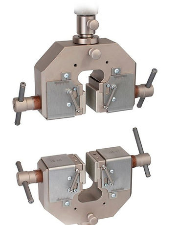
Written by Chris Thomas, Universal Grip Company · Reviewed by Frank Bertini · Updated October 24, 2026
ISO 527-4 is the international standard for the tensile properties of isotropic and orthotropic fibre-reinforced plastic composites: glass, carbon and aramid laminates made from mats, woven fabrics, woven rovings, chopped strands and multidirectional prepreg, in thermoset or thermoplastic matrices. It sits under the general principles of ISO 527-1 and gives the specimens, end tabs, grip distances and speeds for tensile strength, tensile modulus, strain at break and Poisson's ratio. Unidirectional laminates have their own part, ISO 527-5; injection-moulded short-fibre compounds are tested as plastics to ISO 527-2.
This guide covers the current 2023 edition and what the 2021 revision changed; the scope and the moulded-versus-laminated split; the four specimen types with their dimensions, tolerances, gauge lengths and grip distances; end-tab design, the unbonded-tab option and the requirement to record gripping force; speeds and the 0.05 to 0.25 % chord modulus; strain measurement and alignment; conditioning and preparation; the step-by-step procedure; the calculations with a worked example; the common errors and their size; a numeric comparison with ASTM D3039; and the grips, extensometers and machines Universal Grip supplies for composite tensile testing. The composite fixture buyer's guide covers the companion shear, compression and flexure tests, and the ISO standards hub lists every ISO method we equip.
In this guide: What ISO 527-4 Covers and Its Current Edition · Specimen Types: 1B, 2, 3 and 4 · End Tabs, Unbonded Tabs and Gripping Force · Specimen Preparation, Measurement and Conditioning · Test Speeds, Modulus and Strain Measurement · Grips and Load Train for Composite Tensile Testing · Step-by-Step ISO 527-4 Procedure · Calculations and a Worked Example · Common Errors and How Large They Are · ISO 527-4 vs ASTM D3039 · Equipment for ISO 527-4 Composite Tensile Testing · FAQ
What ISO 527-4 Covers and Its Current Edition
ISO 527-4 applies to fibre-reinforced plastics whose reinforcement is not purely unidirectional: chopped-strand and continuous-filament mats, woven fabrics and woven rovings, hybrids, short and milled fibres, multidirectional prepreg lay-ups, and mixed laminates that contain unidirectional layers provided the lay-up is symmetrical. It covers test panels and finished products with glass, carbon or aramid fibres in thermoset or thermoplastic matrices, in laminate thicknesses from 2 to 10 mm. Three neighbours take the rest of the field: ISO 527-5 for unidirectional laminates, ISO 527-2 for injection-moulded short-fibre compounds and ISO 527-3 for films. The split between 527-2 and 527-4 for short-fibre material is the process, not the fibre: a moulded dumb-bell is a plastic, a compression-moulded or laminated sheet cut into specimens is a composite.
The current edition is ISO 527-4:2023, a minor revision of ISO 527-4:2021 that tidied symbols and figures. The 2021 edition was the substantive one: it replaced the 1997 text, added the tapered Type 4 specimen for testing without end tabs, required the gripping force or pressure to be recorded, and added three annexes: Annex B on the tapered specimen, Annex C on unbonded tabs and fine grip faces as an alternative to bonded tabs, and Annex E on correcting the strength of a Type 4 specimen that fails outside its gauge section. Most equipment literature still describes the three-specimen 1997 scheme. EN, BS EN and DIN EN ISO 527-4 are identical adoptions.
Specimen Types: 1B, 2, 3 and 4
ISO 527-4 defines four specimen types. Which one applies depends on the reinforcement and on whether the laminate survives being gripped directly. Dimensions are in millimetres; thickness is the laminate's as-made thickness, 2 to 10 mm, and is not machined.
-
Type 1B, dumb-bell: overall length at least 150 mm, end width 20 ± 0.2 mm, narrow width 10 ± 0.2 mm, parallel length 60 ± 0.5 mm, shoulder radius at least 60 mm, gauge length 50 ± 0.5 mm, grip distance 115 ± 1 mm. For mat, SMC and other materials with short or randomly oriented fibres that fail acceptably at a radius. Continuous-fibre laminates must not use it; the fibres cut at the shoulders start failures there.
-
Type 2, rectangular strip without tabs: overall length at least 250 mm, width 25 ± 0.5 mm or 50 ± 0.5 mm, gauge length 50 ± 1 mm, grip distance 150 ± 1 mm. For fabric and woven-roving laminates gripped directly with fine or smooth faces, or with the unbonded tabs of Annex C. The 50 mm width is for coarse reinforcements, woven roving and chopped-strand mat, where a 25 mm strip cuts too few tows to be representative.
-
Type 3, rectangular strip with bonded end tabs: the same strip as Type 2, 250 mm long and 25 or 50 mm wide, with tabs bonded to both faces at each end; gauge length 50 ± 1 mm, grip distance 136 ± 1 mm measured between the tab ends. For laminates that fail in the grips as Type 2, and for high-strength fabric laminates generally.
-
Type 4, tapered strip without tabs (since 2021): a strip whose gripped ends are wider than the straight gauge section, with a 25 mm gauge length. For continuous-fibre laminates, especially thermoplastic-matrix ones, that cannot be tabbed with a bonded adhesive. If the break falls outside the straight section the strength is recalculated to the local cross-section at the failure plane under Annex E.
Selection path: mat and SMC go to Type 1B; fabric and woven-roving laminates start as Type 2 with fine faces or emery cloth; if specimens fail at the jaw or the grip pressure crushes the laminate, move to Type 3 with bonded tabs; use Type 4 for thermoplastic laminates that will not bond. Test both principal directions of an orthotropic material, at least five valid specimens in each, with the fibre direction on the specimen axis. Width is held to ± 0.5 mm and the thickness should be uniform along the gauge section.
End Tabs, Unbonded Tabs and Gripping Force
End tabs spread the clamping load, stop the grip teeth from cutting surface fibres and move the failure into the gauge section. ISO 527-4 tabs are at least 50 mm long and 1 to 3 mm thick, made from cross-ply or ± 45° glass-fibre laminate or from the material under test, bonded with a structural adhesive, usually a film or paste epoxy, cured at a temperature below the laminate's glass transition so that the laminate is not post-cured by the tabbing operation. The tab faces must be parallel so that the grip clamps evenly, and the tab ends are square: ISO does not permit the bevelled tabs that ASTM D3039 allows. A light abrasion and solvent wipe of tab and laminate decides whether the bond survives; a debonded tab means a jaw failure and an invalid test.
The 2021 edition added Annex C, which allows unbonded tabs, such as emery cloth or loose glass-fibre pads placed between the grip faces and the specimen, or simply fine or smooth grip faces, in place of bonded tabs where they prevent grip failures. The same edition made the gripping force part of the record: the torque applied to screw grips or the manometer pressure on hydraulic and pneumatic grips must be reported, because too little pressure allows slip and too much crushes the laminate and starts the failure under the jaw. Start low on untabbed glass and raise the pressure only until slip stops; tabbed carbon tolerates more.
ISO 527-5, the unidirectional part, uses thinner tabs of 0.5 to 2 mm; labs running both parts should keep the two tab drawings separate.
Specimen Preparation, Measurement and Conditioning
Panels are made to ISO 1268 or taken from the product. Specimens are cut with a diamond or abrasive wheel under coolant, or by water jet, with edges parallel and free of delamination, fibre pull-out and heat damage. The fibre direction is aligned with the specimen axis, and for orthotropic materials sets are cut in both principal directions. Width and thickness are measured to ISO 16012 at three points in the gauge region, at the centre and near each end, with a micrometer reading to 0.01 mm, and the mean cross-section is used in the calculations.
Conditioning follows ISO 291, 23 ± 2 °C and 50 ± 10 % relative humidity, unless the material specification calls for something else. Aerospace and marine laminates are often tested hot-wet; the specimen, tabs and grips are soaked to temperature in an environmental chamber first, the tab adhesive must survive the exposure, and the conditioning state is recorded with the result, since a wet, hot glass-epoxy laminate can lose a third of its room-temperature strength.
Test Speeds, Modulus and Strain Measurement
ISO 527-4 gives the speed in two clauses, one for the Type 1B dumb-bell and one for the rectangular Types 2, 3 and 4. For the rectangular types the test runs at 2 mm/min for modulus and for strength; a faster speed may be used for strength where the material specification allows, and the ISO 527-1 tolerances apply. On a 50 mm gauge length 2 mm/min is a nominal 4 %/min, so a glass-fabric laminate that breaks at 2.5 % strain fails in under a minute. Equipment guides that quote 5 or 10 mm/min for routine control are describing material-specification choices, not the standard's default.
The tensile modulus is the chord, or regression slope, between 0.05 % and 0.25 % strain, the ISO 527-1 interval. ASTM D3039 uses 0.1 to 0.3 %, and the two windows give slightly different numbers on a laminate whose curve is not perfectly linear, so a modulus must be labelled with its standard. On 50 mm the interval spans 25 to 125 µm of extension, which calls for an ISO 9513 class 1 extensometer or strain gauges; crosshead displacement is not acceptable. Poisson's ratio is the negative ratio of transverse to axial strain, taken over a strain interval wider than the modulus window, and needs a transverse strain measurement from a biaxial extensometer, a second strain gauge or a video system.
-
Clip-on extensometers: a 50 mm clip-on extensometer of class 1 for modulus, with a biaxial version for Poisson's ratio. Laminates rich in 0° fibres fail explosively and the extensometer should be removed after the modulus segment or protected.
-
Video and 3D extensometers: a video extensometer follows marks to failure with nothing on the specimen and reads through a chamber window; the Vector 3D extensometer gives axial and transverse strain for Poisson's ratio and shows bending between the two faces.
-
Strain gauges: for cryogenic and high-temperature work and alignment checks, one on each face so bending can be calculated.
Alignment is treated in Annex A, which points to ISO 23788. A strain-gauged alignment coupon with gauges on both faces gives the percent bending, B = |εfront − εback| / |εfront + εback| × 100, and the load train is adjusted until bending is within the agreed limit, usually a few percent.
Grips and Load Train for Composite Tensile Testing
The grip must hold the full tab or gripped length without slip, with uniform pressure, without crushing or bending the laminate. Loads are large: a 25 mm carbon-fabric coupon can need 40 kN and a 50 mm woven-roving glass coupon 70 kN. The choice follows the laminate and the capacity:
-
Hydraulic grips: the first choice for carbon, tabbed Type 3 specimens and anything above 50 kN. The clamping pressure is set on the manometer, which satisfies the 2021 recording requirement directly, stays constant through the test and is repeatable from specimen to specimen. Serrated or diamond-coated faces on bonded tabs; fine-grit faces on untabbed Type 2 glass.
-
Mechanical wedge grips: self-tightening wedges for benchtop frames of 25 to 100 kN; the clamping force rises with the load, which suits glass laminates and Type 1B dumb-bells. Record the initial closing torque. Face choice as for hydraulic grips; smooth faces with emery cloth for thin fabric laminates.
-
Pneumatic grips: for thin laminates and Type 1B specimens below about 10 kN, where constant pressure matters more than capacity.
-
Faces: serrated for bonded tabs, fine grit or smooth with emery cloth for untabbed laminates; face length should cover the full tab.
Every grip ships with adapters for any frame, and the load train should be checked with an alignment coupon after installation. A jaw or tab-transition failure is invalid and the specimen is replaced; three in a row mean the faces, pressure, tabs or alignment need attention.
Step-by-Step ISO 527-4 Procedure
-
1. Prepare the panel to ISO 1268 or take it from the product; cut at least five specimens per direction with a diamond wheel or water jet, edges parallel and undamaged; bond tabs for Type 3 and cure below the laminate's glass transition.
-
2. Condition to ISO 291 or the material specification, including any moisture conditioning, and record it.
-
3. Measure width and thickness at three points in the gauge region to 0.01 mm and record the mean cross-section; mark the gauge length or fit strain gauges.
-
4. Set the machine: a load cell and grips matched to the expected force, the grip distance for the type (115 mm for 1B, 150 mm for Type 2, 136 mm between tab ends for Type 3), the grip pressure or torque, the extensometer and the speed of 2 mm/min.
-
5. Mount the specimen centred in both grips with the full tab length inside the faces, apply the gripping pressure and record it, and apply a preload below 0.05 % strain or 1 % of the expected strength.
-
6. Run at 2 mm/min, recording force and axial strain, and transverse strain if Poisson's ratio is required; remove a contact extensometer after the modulus segment on laminates that fail explosively.
-
7. Check the failure location: gauge-section failures are valid; jaw, tab-transition and slipped specimens are discarded and replaced; for Type 4 note the position of the break for the Annex E correction.
-
8. Calculate stress on the mean original cross-section, the chord modulus between 0.05 and 0.25 %, Poisson's ratio, strain at break, and the mean, standard deviation and number of valid results per direction.
-
9. Report the standard part, material and lay-up, specimen type and dimensions, tab material and adhesive or the Annex C method, gripping force or pressure, grip faces, alignment method, extensometer and gauge length, speed, conditioning, failure locations and rejected specimens.
Calculations and a Worked Example
With F the force in newtons, b the mean width and h the mean thickness in millimetres, and strains as fractions from the extensometer:
-
Tensile stress: σ = F / (b × h), in MPa; tensile strength σm is the first local maximum of stress.
-
Tensile modulus: Et = (σ2 − σ1) / (ε2 − ε1) with ε1 = 0.0005 and ε2 = 0.0025, or the least-squares slope over the same interval.
-
Poisson's ratio: µ = −Δεn / Δε, the ratio of the transverse strain change to the axial strain change over the chosen interval.
-
Strain at break: εb from the extensometer or marks at the moment of fracture.
-
Type 4 correction (Annex E): if the break is outside the straight gauge section, the strength is recalculated using the specimen width at the failure plane instead of the gauge-section width.
Worked example, a Type 3 glass-fabric epoxy laminate 25 mm wide. The mean width from three readings is 25.02 mm and the mean thickness 2.48 mm, so the cross-section is 25.02 × 2.48 = 62.05 mm². At 2 mm/min the force at 0.05 % axial strain is 608 N and at 0.25 % strain 3,413 N: σ1 = 608 / 62.05 = 9.80 MPa and σ2 = 3,413 / 62.05 = 55.00 MPa, so Et = (55.00 − 9.80) / (0.0025 − 0.0005) = 45.20 / 0.002 = 22,600 MPa, reported as 22.6 GPa. Over the same interval the transverse strain changes by −0.000268, so µ = 0.000268 / 0.002 = 0.134. The maximum force is 27.9 kN, giving σm = 27,900 / 62.05 = 450 MPa, and the extensometer reads 2.41 % at fracture. The failure is in the gauge section, so the specimen is valid; five such results are averaged and the standard deviation reported.
Common Errors and How Large They Are
-
Jaw or transition failures counted as valid: they are grip artefacts and must be replaced; counting them typically pulls the mean strength down by 10 to 20 % and doubles the scatter.
-
Modulus from crosshead displacement: grip seating and load-train compliance on a 150 mm grip distance make the apparent strain two to three times the true strain; the modulus reads 50 to 70 % low. Use a class 1 extensometer or strain gauges.
-
Using the ASTM D3039 window and calling it ISO: 0.1 to 0.3 % and 0.05 to 0.25 % give moduli that differ by a few percent on curved laminate curves; report the window with the number.
-
Tabs debonding at temperature or after moisture conditioning: choose an adhesive that survives the exposure and cure below the laminate's glass transition, or use the Annex C unbonded option.
-
Gripping pressure not recorded or set by habit: too low gives slip and a false plateau, too high crushes the laminate under the jaw; the 2021 edition requires the value in the report.
-
25 mm specimens on coarse woven roving or mat: too few tows per width; results scatter and run low. Use the 50 mm width the standard provides for coarse reinforcements.
-
Testing one direction of an orthotropic laminate: warp and weft can differ by 30 % or more; both principal directions are required.
ISO 527-4 vs ASTM D3039
ISO 527-4 and ASTM D3039 cover the same laminates and are often requested side by side, but the results are not fully comparable. The differences that matter:
-
Scope: ISO 527-4 covers non-unidirectional laminates and sends unidirectional material to ISO 527-5; D3039 covers all polymer-matrix composites, unidirectional included, in one method.
-
Specimens: ISO defines Type 1B (150 × 20/10 mm), Type 2 and 3 (at least 250 × 25 or 50 mm, grip distance 150 or 136 mm) and the tapered Type 4; D3039 uses straight strips with recommended geometries of 25 × 250 × 2.5 mm for fabric laminates, 15 × 250 × 1 mm for 0° and 25 × 175 × 2 mm for 90° coupons.
-
Thickness: ISO specimens cover 2 to 10 mm; D3039 has no fixed range.
-
Tabs: ISO at least 50 mm long, 1 to 3 mm thick, square ends only, with unbonded tabs allowed under Annex C; ASTM tabs are optional and may be bevelled between 5 and 90°, 7° being typical, with 56 mm long, 1.5 mm thick tabs common.
-
Gauge length: ISO 50 mm (25 mm for Type 4); ASTM leaves it to the user, usually 25 to 50 mm.
-
Speed: ISO 2 mm/min; ASTM 2 mm/min or a strain rate of 0.01 per minute, set so that failure occurs in 1 to 10 minutes.
-
Modulus: ISO chord between 0.05 and 0.25 % strain; ASTM chord between 0.1 and 0.3 % (1,000 to 3,000 microstrain).
-
Extensometer: ISO 9513 class 1; ASTM E83 class B-1.
-
Failure reporting: ISO records the location and rejects jaw and transition failures; ASTM uses three-letter failure codes such as LGM or GAT.
-
Tolerances: ISO width ± 0.5 mm; ASTM width ± 1 % and thickness ± 4 %.
A lab serving both keeps two methods in the software, one with each modulus window; a D3039 modulus is not an ISO 527-4 modulus.
Equipment for ISO 527-4 Composite Tensile Testing
Capacity is set by the strongest laminate and the widest specimen the lab will see. Glass-fabric laminates 25 mm wide need 20 to 35 kN, carbon-fabric laminates 25 mm wide 40 to 50 kN, 50 mm woven-roving coupons 60 to 80 kN, and Type 1B mat and SMC dumb-bells only 3 to 6 kN. A 50 kN frame covers most glass work, 100 kN covers 25 mm carbon and 200 kN covers 50 mm coupons; fit a smaller load cell for the dumb-bells.
-
Machines: the 50 kN benchtop UTM covers glass laminates and Type 1B work; the 100 kN benchtop UTM covers 25 mm carbon coupons; the 200 kN floor-standing UTM covers 50 mm woven-roving coupons and leaves headroom for hydraulic grips. The 25 kN benchtop suits a glass-only laboratory.
-
Grips: hydraulic grips for carbon and tabbed specimens, mechanical wedge grips for glass on benchtop frames, pneumatic grips for thin laminates and Type 1B; serrated, fine-grit and smooth faces to suit tabbed and untabbed specimens.
-
Strain: a 50 mm class 1 clip-on extensometer with a biaxial option for Poisson's ratio, a video extensometer for strain to failure and chamber work, and the Vector 3D extensometer for axial and transverse strain with bending shown between faces.
-
Environment: an environmental chamber for hot-wet and sub-zero tests with the extensometer reading through the window.
-
Companion composite fixtures: compression to ASTM D6641 and D3410, short-beam shear to ASTM D2344, V-notch shear to ASTM D5379, flexure to ASTM D7264, open-hole tension and compression to ASTM D5766 and D6484; see the shear fixtures and compression fixtures pages.
See also ISO 527-1, ISO 527-5, ASTM D3039 and the tensile testing page.
ISO 527-4 FAQ
What materials does ISO 527-4 cover?
Isotropic and orthotropic fibre-reinforced plastics: mat, woven-fabric, woven-roving, chopped-strand and multidirectional laminates, 2 to 10 mm thick, with glass, carbon or aramid fibres. Unidirectional laminates go to ISO 527-5 and injection-moulded compounds to ISO 527-2.
What are the ISO 527-4 specimen types?
Type 1B, a dumb-bell 150 mm long with 20 mm ends and a 10 mm neck for mat and SMC; Type 2, a strip at least 250 mm long and 25 or 50 mm wide without tabs; Type 3, the same strip with bonded end tabs; and Type 4, a tapered strip without tabs with a 25 mm gauge length, added in 2021 for laminates that cannot be tabbed.
What is the ISO 527-4 test speed?
2 mm/min for both modulus and strength on the rectangular Types 2, 3 and 4, which is a nominal 4 %/min on the 50 mm gauge length. A faster strength speed may be used only where the material specification allows it, and the speed is reported with the result.
How is the tensile modulus defined in ISO 527-4?
As the chord or regression slope between 0.05 % and 0.25 % axial strain, measured on a 50 mm gauge length with an ISO 9513 class 1 extensometer or strain gauges. ASTM D3039 uses 0.1 to 0.3 %, so the two moduli are not interchangeable.
What end tabs does ISO 527-4 require?
Tabs at least 50 mm long and 1 to 3 mm thick, made from cross-ply or ±45° glass laminate or the material itself, bonded with a structural adhesive cured below the laminate's glass transition, with square ends; bevelled tabs are not permitted. Annex C allows unbonded tabs such as emery cloth or fine grip faces instead.
Does ISO 527-4 require the gripping pressure to be recorded?
Yes, since the 2021 edition: the torque on screw grips or the manometer pressure on hydraulic or pneumatic grips is part of the test report, because slip and crushing both start at the grip.
What grip distance is used in ISO 527-4?
115 mm for the Type 1B dumb-bell, 150 mm for the untabbed Type 2 strip and 136 mm between tab ends for the tabbed Type 3 strip, each with a 50 mm gauge length.
How many specimens does ISO 527-4 need?
At least five valid specimens per direction, and both principal directions for orthotropic laminates. Specimens that fail in the grips, at the tab transition or that slip are discarded and replaced.
Which grips are used for ISO 527-4 composite tensile tests?
Hydraulic grips for carbon and tabbed specimens above about 50 kN, mechanical wedge grips for glass laminates on benchtop frames, and pneumatic grips for thin laminates and Type 1B dumb-bells, with serrated faces on tabs and fine-grit or smooth faces on untabbed laminates.
What machine capacity do I need for ISO 527-4?
Roughly 20 to 35 kN for 25 mm glass-fabric laminates, 40 to 50 kN for 25 mm carbon-fabric laminates, 60 to 80 kN for 50 mm woven-roving coupons and under 6 kN for Type 1B mat or SMC. A 50 kN frame covers most glass work, 100 kN covers 25 mm carbon and 200 kN covers 50 mm coupons with hydraulic grips.
What is the difference between ISO 527-4 and ASTM D3039?
ISO 527-4 excludes unidirectional laminates, fixes specimen types with a 2 to 10 mm thickness range, requires square-ended tabs 1 to 3 mm thick and uses a 0.05 to 0.25 % modulus window; D3039 covers all laminates, allows bevelled tabs, uses a 0.1 to 0.3 % window and reports three-letter failure codes. Both run at 2 mm/min with at least five specimens.
What changed in ISO 527-4:2021 and 2023?
The 2021 edition replaced the 1997 text, added the tapered Type 4 specimen, required gripping force to be recorded and added annexes on unbonded tabs and failure-location correction; 2023 is a minor revision of symbols and figures.
Need hydraulic or wedge grips, an alignment-checked load train, extensometers or a complete system for ISO 527-4? Contact Universal Grip with your laminate, specimen type and expected strength and we will quote the right setup.